
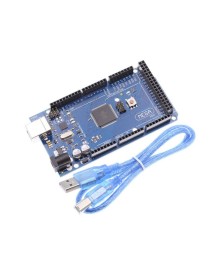
Board specifications:
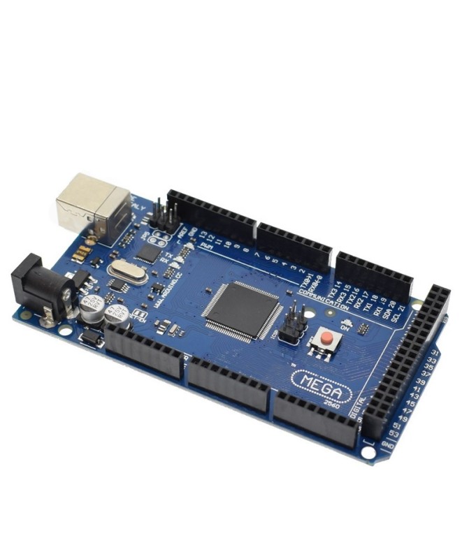
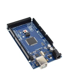
Arduino Mega 2560 is a microcontroller development board, built on the basis of the microcontroller ATmega2560. On female header strips with a 2.54mm pitch, 54 digital input/output ports and 16 analog inputs are brought out, as well as 5V, 3.3V and GND. Of the digital I/O ports, 14 can be used as PWM (Pulse Width Modulation). On pin headers, the inputs of the ICSP connector for programming the microcontroller and the USB-UART chip are brought out. Indicator LEDs are available – ON(indicates the presence of 5V supply voltage) , TX and RX (indicate transmit/receive signals of the serial communication) and L (connected to GPIO 13 microcontroller pin). Near the USB connector is located a RESET button, used for restarting the microcontroller board. It is connected to the RESET pin brought out on a female header strip.
Power supply for the Arduino UNO R3 is provided via the USB connector or DC connector 5.5x2.1mm. The power supply range for the DC connector is 7-12VDC.
Communication and programming of the Arduino UNO R3 is done via the USB-B connector, and is handled by the microcontroller chip ATmega16U2, programmed as USB to Serial. The serial communication signals RX and TX are brought out on GPIO 0 and GPIO 1.
The following additional signals are brought out on the female header strips:
Board specifications: