Board specifications:
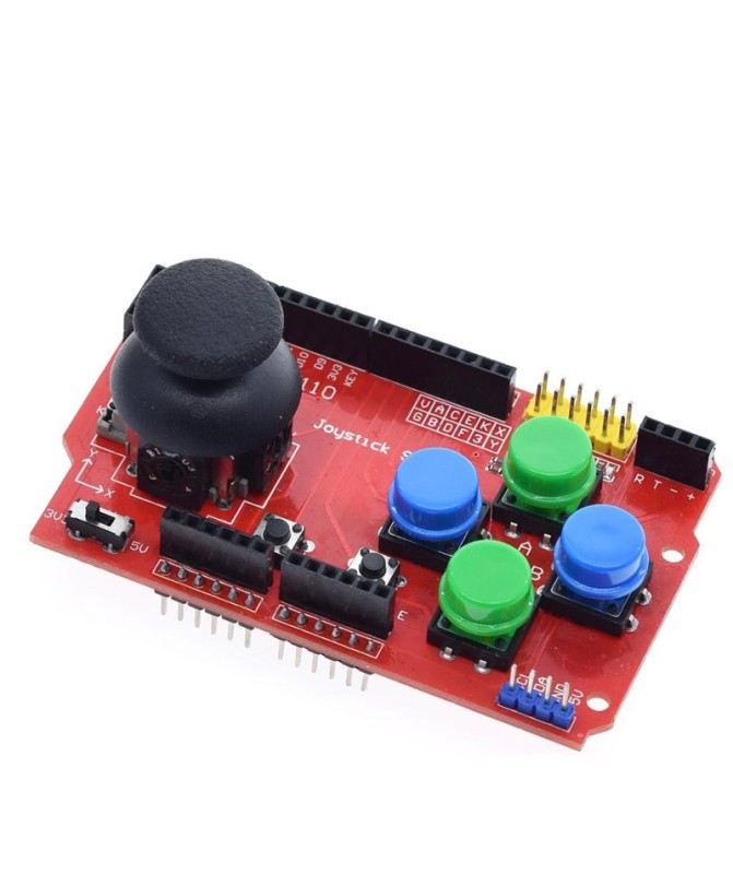
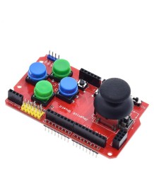
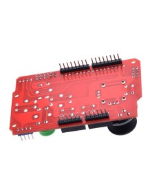
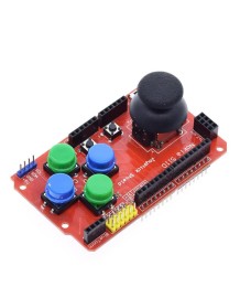
The Arduino Gamepad Joystick Keypad Shield PS2 provides an easy way to create projects for Arduino with a joystick and buttons. It is possible to create games and interfaces embedded on an Arduino microcontroller board. In this case, an I2C LCD 5110 screen is used. Remote control of devices via wireless communication is also possible. In this case, an additional nRF24L01 module is used.
The Arduino Gamepad Joystick Keypad Shield PS2 is powered via the pin headers from the available Arduino board. To ensure proper power supply for some functionalities, a slide switch has been added to select the voltage for the nRF24L01 and LCD 5110.
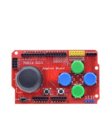
The board features 7 push buttons. 4 buttons (A, B, C, D) are arranged in a rhomboid shape, 2 (E, F) buttons are placed next to each other. The last button is built into the joystick. All buttons are connected to digital pins D2-D8. When pressed, they provide a low level, while the high level is provided by pull-up resistors. All 7 buttons, along with the joystick and supply voltages, are also brought out to an additional 6x2 pin header (the yellow header). The functionality of each pin on the header is printed in white on the board.
The two-axis joystick has two built-in analog potentiometers and a button. Signals from the two potentiometers are fed to analog pins A0 and A1 of the connected microcontroller board. In the middle position of the joystick, the analog values of A0 and A1 are equal to half the supply voltage. Accordingly, at the extreme positions, the voltages are GND or the supply voltage.
The Arduino Gamepad Joystick Keypad Shield PS2 has a specialized socket header for connecting an LCD 5110 screen. The necessary pins (printed in white on the board) are set using known libraries.
The Arduino Gamepad Joystick Keypad Shield PS2 has a specialized socket header for connecting a wireless nRF24L01 module. The pin layout is standard, as it uses the communication buses of the SPI interface (MOSI, MISO, SCK etc.).
Board specifications: